Mastering the SiLabs C8051 Microcontroller
|
|
MODBUS – ToF200 Distance Sensor
MODBUS RTU protocol is the industry standard for reliable serial communication among devices via RS232, RS485, etc. In MODBUS RTU, data from and to a device is sent and received in a specific packet format that encapsulates ID, function code, location address, number of bytes, data and a CRC field. If one or some fields of this encapsulation is wrong then the entire frame is discarded as garbage.
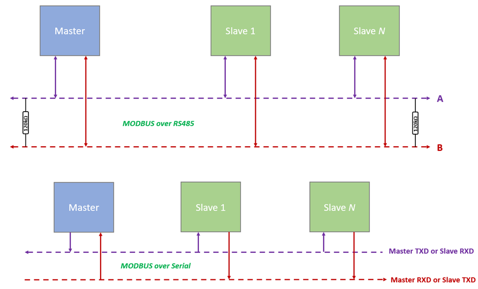
Shown above are two common types of MODBUS hardware implementation. The first one utilizes RS485 as a medium for longer range while the latter is mostly seen in short-range and onboard components. The basic MODBUS protocol is the same in both cases except for the medium.
MODBUS is itself a large topic to discuss here and so to know more about MODBUS, visit these links:
- https://en.wikipedia.org/wiki/Modbus
- https://modbus.org/docs/PI_MBUS_300.pdf
- https://modbus.org/docs/Modbus_Application_Protocol_V1_1b.pdf
Code
ToF200.h
 #define ToF200_TX_data_packet_size                    8
 #define ToF200_RX_data_packet_size                    16

 #define ToF200_slave_default_ID                       0x01

 //registers
 #define ToF200_special_register                       0x0001
 #define ToF200_slave_ID_register                      0x0002
 #define ToF200_baud_rate_register                     0x0003
 #define ToF200_range_precision_register               0x0004
 #define ToF200_output_control_register                0x0005
 #define ToF200_load_calibration_register              0x0006
 #define ToF200_offset_correction_register             0x0007
 #define ToF200_xtalk_correction_register              0x0008
 #define ToF200_i2c_enable_register                    0x0009
 #define ToF200_measurement_register                   0x0010
 #define ToF200_offset_calibration_register            0x0020
 #define ToF200_xtalk_calibration_register             0x0021

 //parameters
 #define ToF200_restore_default                        0xAA55
 #define ToF200_reboot                                 0x1000
 #define ToF200_comm_test                              0x0000

 #define ToF200_baud_rate_115200                       0x0000
 #define ToF200_baud_rate_38400                        0x0001
 #define ToF200_baud_rate_9600                         0x0002

 #define ToF200_high_precision_1200mm                  0x0001
 #define ToF200_medium_precision_2000mm                0x0002
 #define ToF200_low_precision_1200mm                   0x0003

 #define ToF200_do_not_load_calibration                0x0000
 #define ToF200_load_calibration                       0x0001

 #define ToF200_i2c_not_prohibited                     0x0000
 #define ToF200_i2c_prohibited                         0x0001

 //other constant parameters
 #define ToF200_default_max_distance                   2000

 #define MODBUS_read_holding_registers_function_code   0x03
 #define MODBUS_write_single_register_function_code    0x06

 unsigned char cnt;
 unsigned char rx_buffer[ToF200_RX_data_packet_size];

 unsigned int make_word(unsigned char HB, unsigned char LB);
 void get_HB_LB(unsigned int value, unsigned char *HB, unsigned char *LB);
 unsigned int MODBUS_RTU_CRC16(unsigned char *data_input, unsigned char data_length);
 void flush_RX_buffer(void);
 void MODBUS_TX(unsigned char slave_ID, unsigned char function_code, unsigned char reg, unsigned char value);
 unsigned int ToF_get_range(void);
ToF200.c
 #include "ToF200.h"

 unsigned int make_word(unsigned char HB, unsigned char LB)
 {
     unsigned int tmp = 0;

     tmp = HB;
     tmp <<= 8;
     tmp |= LB;

     return tmp;
 }

 void get_HB_LB(unsigned int value, unsigned char *HB, unsigned char *LB)
 {
     *LB = (unsigned char)(value & 0x00FF);
     *HB = (unsigned char)((value & 0xFF00) >> 8);
 }

 unsigned int MODBUS_RTU_CRC16(unsigned char *data_input, unsigned char data_length)
 {
     unsigned char n = 8;
     unsigned char s = 0;
     unsigned int CRC_word = 0xFFFF;

     for(s = 0; s < data_length; s++)
     {
       CRC_word ^= ((unsigned int)data_input[s]);

       n = 8;
       while(n > 0)
       {
         if((CRC_word & 0x0001) == 0)
         {
           CRC_word >>= 1;
         }

         else
         {
           CRC_word >>= 1;
           CRC_word ^= 0xA001;
         }

         n--;
       }
     }

     return CRC_word;
 }

 void flush_RX_buffer(void)
 {
     signed char s = (ToF200_TX_data_packet_size - 1);

     while(s > -1)
     {
         rx_buffer[s] = 0x00;
         s--;
     };
 }

 void MODBUS_TX(unsigned char slave_ID, unsigned char function_code, unsigned char reg, unsigned char value)
 {
     unsigned char i  = 0x00;
     unsigned char lb = 0x00;
     unsigned char hb = 0x00;
     unsigned int temp = 0x0000;

     unsigned char tx_buffer[ToF200_TX_data_packet_size];

     tx_buffer[0x00] = slave_ID;
     tx_buffer[0x01] = function_code;

     get_HB_LB(reg, &hb, &lb);

     tx_buffer[0x02] = hb;
     tx_buffer[0x03] = lb;

     get_HB_LB(value, &hb, &lb);

     tx_buffer[0x04] = hb;
     tx_buffer[0x05] = lb;

     temp = MODBUS_RTU_CRC16(tx_buffer, 6);
     get_HB_LB(temp, &hb, &lb);

     tx_buffer[0x06] = lb;
     tx_buffer[0x07] = hb;

     flush_RX_buffer();

     for(i = 0; i < ToF200_TX_data_packet_size; i++)
     {
         UART_Write(tx_buffer[i]);
     }

     cnt = 0x00;
     delay_ms(40);
 }

 unsigned int ToF_get_range(void)
 {
     unsigned int CRC_1 = 0x0000;
     unsigned int CRC_2 = 0x0000;

     unsigned int distance = 5000;

     MODBUS_TX(ToF200_slave_default_ID,
               MODBUS_read_holding_registers_function_code,
               ToF200_measurement_register,
               0x0001);

     if(rx_buffer[0x00] == ToF200_slave_default_ID)
     {
         if(rx_buffer[0x01] == MODBUS_read_holding_registers_function_code)
         {
             if(rx_buffer[0x02] == 0x02)
             {
                 CRC_1 = MODBUS_RTU_CRC16(rx_buffer, 5);
                 CRC_2 = make_word(rx_buffer[0x06], rx_buffer[0x05]);

                 if(CRC_1 == CRC_2)
                 {
                     distance = make_word(rx_buffer[0x03], rx_buffer[0x04]);
                     if(distance > ToF200_default_max_distance)
                     {
                         distance = 40000;
                     }
                 }

                 else
                 {
                     distance = 40000;
                 }
             }
         }
     }

     return distance;
 }
main.c
 #include "ToF200.c"

 #define LED_DOUT P1_6_bit
 #define  LED_CLK P1_5_bit
 #define  LED_LATCH P1_7_bit

 unsigned int d = 0;
 unsigned char i = 0;
 unsigned char value = 0;

 const unsigned char code segment_code[12] =
 {
   0xC0, // 0
   0xF9, // 1
   0xA4, // 2
   0xB0, // 3
   0x99, // 4
   0x92, // 5
   0x82, // 6
   0xF8, // 7
   0x80, // 8
   0x90, // 9
   0x7F, // .
   0xBF  // -
 };

 const unsigned char code display_pos[4] =
 {
   0xF7, //1st Display
   0xFB, //2nd Display
   0xFD, //3rd Display
   0xFE  //4th Display
 };

 void PCA_Init(void);
 void Timer_Init(void);
 void Port_IO_Init(void);
 void Oscillator_Init(void);
 void Interrupts_Init(void);
 void Init_Device(void);
 void write_74HC595(unsigned char send_data);
 void segment_write(unsigned char disp, unsigned char pos);

 void UART0_ISR(void)
 iv IVT_ADDR_ES0
 ilevel 0
 ics ICS_AUTO
 {
     rx_buffer[cnt++] = UART_Read();
     RI0_bit = 0;
 }

 void Timer_ISR(void)
 iv IVT_ADDR_ET3
 ilevel 1
 ics ICS_AUTO
 {
     switch(i)
     {
         case 0:
         {
             value = (d / 1000);
             break;
         }
         case 1:
         {
             value = ((d % 1000) / 100);
             break;
         }
         case 2:
         {
             value = ((d % 100) / 10);
             break;
         }
         case 3:
         {
             value = (d % 10);
             break;
         }
     }

     if(d >= 40000)
     {
         segment_write(11, i);
     }
     else
     {
         segment_write(value, i);
     }

     i++;

     if(i > 3)
     {
        i = 0;
     }

     TMR3CN &= 0x7F;
 }

 void main(void)
 {
      Init_Device();

      while(1)
      {
          d = ((float)ToF_get_range());
          delay_ms(400);
      };
 }

 void PCA_Init(void)
 {
     PCA0MD &= ~0x40;
     PCA0MD = 0x00;
 }

 void Timer_Init(void)
 {
     TMR3CN = 0x04;
     TMR3RLL = 0x02;
     TMR3RLH = 0xFC;
 }

 void Port_IO_Init(void)
 {
     // P0.0  -  Unassigned,  Open-Drain, Digital
     // P0.1  -  Unassigned,  Open-Drain, Digital
     // P0.2  -  Unassigned,  Open-Drain, Digital
     // P0.3  -  Unassigned,  Open-Drain, Digital
     // P0.4  -  TX0 (UART0), Push-Pull,  Digital
     // P0.5  -  RX0 (UART0), Push-Pull,  Digital
     // P0.6  -  Unassigned,  Open-Drain, Digital
     // P0.7  -  Unassigned,  Open-Drain, Digital

     // P1.0  -  Unassigned,  Open-Drain, Digital
     // P1.1  -  Unassigned,  Open-Drain, Digital
     // P1.2  -  Unassigned,  Open-Drain, Digital
     // P1.3  -  Unassigned,  Open-Drain, Digital
     // P1.4  -  Unassigned,  Open-Drain, Digital
     // P1.5  -  Skipped,     Push-Pull,  Digital
     // P1.6  -  Skipped,     Push-Pull,  Digital
     // P1.7  -  Skipped,     Push-Pull,  Digital

     P0MDOUT = 0x30;
     P1MDOUT = 0xE0;
     P1SKIP = 0xE0;
     XBR0 = 0x01;
     XBR1 = 0x40;
 }

 void Oscillator_Init(void)
 {
     OSCICN = 0x82;
 }

 void Interrupts_Init(void)
 {
     IE = 0x90;
     EIE1 = 0x80;
 }

 void Init_Device(void)
 {
     PCA_Init();
     Timer_Init();
     Port_IO_Init();
     Oscillator_Init();
     Interrupts_Init();
     UART1_Init(115200);
 }

 void write_74HC595(unsigned char send_data)
 {
     signed char clks = 0x08;

     while(clks > 0)
     {
         if((send_data & 0x80) == 0x00)
         {
           LED_DOUT = 0;
         }
         else
         {
           LED_DOUT = 1;
         }

         LED_CLK = 0;
         send_data <<= 1;
         clks--;
         LED_CLK = 1;
     }
 }

 void segment_write(unsigned char disp, unsigned char pos)
 {
     LED_LATCH = 0;
     write_74HC595(segment_code[disp]);
     write_74HC595(display_pos[pos]);
     LED_LATCH = 1;
 }
Schematic
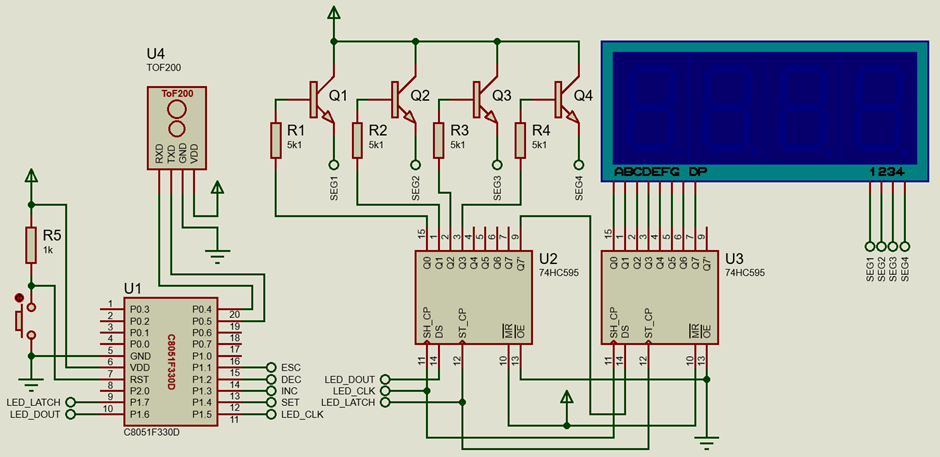
Explanation
In this example, a ToF200 IR rangefinder sensor is used. This sensor communicates via MODBUS RTU frames over UART medium. Therefore, we would need to set up the UART peripheral and UART reception interrupt.
 void Port_IO_Init(void)
 {
     // P0.4  -  TX0 (UART0), Push-Pull,  Digital
     // P0.5  -  RX0 (UART0), Push-Pull,  Digital

     // P1.5  -  Skipped,     Push-Pull,  Digital
     // P1.6  -  Skipped,     Push-Pull,  Digital
     // P1.7  -  Skipped,     Push-Pull,  Digital

     P0MDOUT = 0x30;
     P1MDOUT = 0xE0;
     P1SKIP = 0xE0;
     XBR0 = 0x01;
     XBR1 = 0x40;
 }

 void Interrupts_Init(void)
 {
     IE = 0x90;
     EIE1 = 0x80;
 }

 void Init_Device(void)
 {
     PCA_Init();
     Timer_Init();
     Port_IO_Init();
     Oscillator_Init();
     Interrupts_Init();
     UART1_Init(115200);
 }
The ToF200.h header file describes the functions, registers and parameter values. The codes in ToF200.c source file is what we need to understand. The following functions are typical data manipulation functions. Of these, the MODBUS_RTU_CRC16 function is a bit critical because it generates CRC value when MODBUS frame data is passed to it. This function has been described by MODBUS documentation and so we can simply avoid trying to recreate it on our own.
 unsigned int make_word(unsigned char HB, unsigned char LB);
 void get_HB_LB(unsigned int value, unsigned char *HB, unsigned char *LB);
 unsigned int MODBUS_RTU_CRC16(unsigned char *data_input, unsigned char data_length);
 void flush_RX_buffer(void);
The sensor will send out data when it is asked to return distance. To do so, we have to use the following function.
 void MODBUS_TX(unsigned char slave_ID, unsigned char function_code, unsigned char reg, unsigned char value)
 {
     unsigned char i  = 0x00;
     unsigned char lb = 0x00;
     unsigned char hb = 0x00;
     unsigned int temp = 0x0000;

     unsigned char tx_buffer[ToF200_TX_data_packet_size];

     tx_buffer[0x00] = slave_ID;
     tx_buffer[0x01] = function_code;

     get_HB_LB(reg, &hb, &lb);
     tx_buffer[0x02] = hb;
     tx_buffer[0x03] = lb;

     get_HB_LB(value, &hb, &lb);
     tx_buffer[0x04] = hb;
     tx_buffer[0x05] = lb;

     temp = MODBUS_RTU_CRC16(tx_buffer, 6);
     get_HB_LB(temp, &hb, &lb);
     tx_buffer[0x06] = lb;
     tx_buffer[0x07] = hb;

     flush_RX_buffer();

     for(i = 0; i < ToF200_TX_data_packet_size; i++)
     {
         UART_Write(tx_buffer[i]);
     }

     cnt = 0x00;
     delay_ms(40);
 }
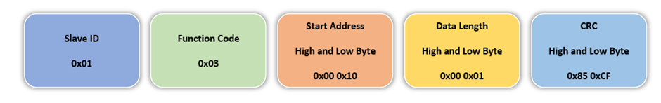
What this function does is simply transmit data from our C8051F330D microcontroller to the ToF200 sensor in the following MODBUS RTU frame format. The first byte is the slave ID followed by the holding register read function, the register to be accessed, data length and CRC high and low bytes computed from these values. Before sending these bytes, the reception buffer array, rx_buffer which would hold the data from the sensor is flushed or cleared of any previous value and the byte counter variable cnt is set to zero.
The data received from the sensor is read using the UART RX interrupt. Whenever a new byte is received by the microcontroller’s UART RX pin, an interrupt is triggered. The received bytes are stored in a buffer array.
 void UART0_ISR(void)
 iv IVT_ADDR_ES0
 ilevel 0
 ics ICS_AUTO
 {
     rx_buffer[cnt++] = UART_Read();
     RI0_bit = 0;
 }
The received data buffer array is then processed to compute distance. The following function returns the range of objects detected by the sensor.
 unsigned int ToF_get_range(void)
 {
     unsigned int CRC_1 = 0x0000;
     unsigned int CRC_2 = 0x0000;
     unsigned int distance = 5000;

     MODBUS_TX(ToF200_slave_default_ID,
               MODBUS_read_holding_registers_function_code,
               ToF200_measurement_register,
               0x0001);

     if(rx_buffer[0x00] == ToF200_slave_default_ID)
     {
         if(rx_buffer[0x01] == MODBUS_read_holding_registers_function_code)
         {
             if(rx_buffer[0x02] == 0x02)
             {
                 CRC_1 = MODBUS_RTU_CRC16(rx_buffer, 5);
                 CRC_2 = make_word(rx_buffer[0x06], rx_buffer[0x05]);
                 if(CRC_1 == CRC_2)
                 {
                     distance = make_word(rx_buffer[0x03], rx_buffer[0x04]);
                     if(distance > ToF200_default_max_distance)
                     {
                         distance = 40000;
                     }
                 }

                 else
                 {
                     distance = 40000;
                 }
             }
         }
     }

     return distance;
 }
Firstly, the function transmits commands to the sensor to return range data. After that, the sensor begins transmitting range data and thus, UART RX interrupt triggers. Data is likely to be received in the following frame format.
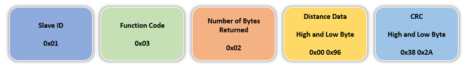
Inside the ToF_get_range function, slave ID, function code and the number of returned bytes are checked against what they should be. If these are okay, the received CRC value is checked against the computed CRC value. If both of these values match then the distance value is read and returned.
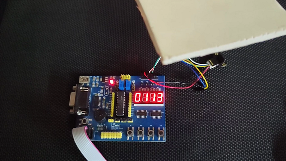
Inside the main loop, the distance is read every 400ms and the read data is shown on the onboard seven-segment LED display.
 void main(void)
 {
      Init_Device();

      while(1)
      {
          d = ((float)ToF_get_range());
          delay_ms(400);
      };
 }
Demo
|
|
Thanks for the feedback….