Mastering the SiLabs C8051 Microcontroller
|
|
PCA in Capture Mode – TCS3200 Colour Sensor
In many applications, we need to measure pulse widths and frequencies of signals and in such cases, accurate measurement can be done using a capture module. We can also use external interrupts and timers too but with capture hardware things are far more accurate and precise.
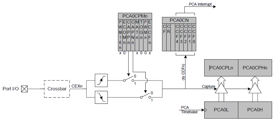
The block diagram below shows the PCA hardware in edge-capture mode. With a defined time base, PCA keeps ticking. When there is an edge capture event, PCA counter values are copied to capture-compare registers. The type of edge to be captured and many other things can be set by tweaking internal registers and it is possible to capture falling and rising edges. Capturing consecutive like edges results in deducing period or frequency while capturing consecutive edges that have different polarities result in deducing pulse width.
Code
 #include "Waveshare_RGB_LCD.c"
 #include "lcd_print_rgb.c"

 #define RED_filter      0x00
 #define BLUE_filter     0x01
 #define CLEAR_filter    0x02
 #define GREEN_filter    0x03

 #define S2              P1_4_bit
 #define S3              P1_5_bit

 unsigned long count = 0;
 unsigned int overflow = 0;
 unsigned int past_capture = 0;
 unsigned int current_capture = 0;

 void PCA_Init(void);
 void Voltage_Reference_Init(void);
 void Port_IO_Init(void);
 void Oscillator_Init(void);
 void Interrupts_Init(void);
 void Init_Device(void);
 unsigned int get_capture_count(void);

 void PCA0_ISR(void)
 iv IVT_ADDR_EPCA0
 ilevel 0
 ics ICS_AUTO
 {
     if(CF_bit)
     {
         overflow++;
         CF_bit = 0;
     }

     if(CCF0_bit)
     {
         current_capture = get_capture_count();
         count = ((overflow << 16) + (current_capture - past_capture));
         past_capture = current_capture;
         overflow = 0x00000;
         current_capture = 0;
         CCF0_bit = 0;
     }
 }

 void main(void)
 {
     unsigned long f = 0;
     unsigned long fr = 0;
     unsigned long fg = 0;
     unsigned long fb = 0;
     unsigned long fc = 0;
     unsigned char mode = 0;

     Init_Device();
     RGB_LCD_init();
     LCD_clear_home();

     LCD_goto(0, 0);
     LCD_putstr(" R%  G%  B%  fC");

     while(1)
     {
         switch(mode)
         {
             case RED_filter:
             {
                 S2 = 0;
                 S3 = 0;
                 break;
             }
             case BLUE_filter:
             {
                 S2 = 0;
                 S3 = 1;
                 break;
             }
             case CLEAR_filter:
             {
                 S2 = 1;
                 S3 = 0;
                 break;
             }
             case GREEN_filter:
             {
                 S2 = 1;
                 S3 = 1;
                 break;
             }
         }
         delay_ms(100);

         f = (1020833 / ((float)count));

         switch(mode)
         {
             case RED_filter:
             {
                 fr = f;
                 break;
             }
             case BLUE_filter:
             {
                 fb = f;
                 break;
             }
             case CLEAR_filter:
             {
                 fc = f;
                 break;
             }
             case GREEN_filter:
             {
                 fg = f;
                 break;
             }
         }

         mode++;

         if(mode > 3)
         {
             fr = (((float)fr / (float)fc) * 100);
             fg = (((float)fg / (float)fc) * 100);
             fb = (((float)fb / (float)fc) * 100);

             print_C(0, 1, fr);
             print_C(4, 1, fg);
             print_C(8, 1, fb);
             print_I(12, 1, fc);

             fr <<= 1;
             fg <<= 1;
             fb <<= 1;
             set_RGB(fr, fg, fb);

             mode = 0;
             delay_ms(400);
         }
     };
 }

 void PCA_Init(void)
 {
     PCA0CN = 0x40;
     PCA0MD &= ~0x40;
     PCA0MD = 0x01;
     PCA0CPM0 = 0x11;
 }

 void Voltage_Reference_Init(void)
 {
     REF0CN = 0x08;
 }

 void Port_IO_Init(void)
 {
     // P0.0  -  CEX0 (PCA),  Open-Drain, Digital
     // P0.1  -  Unassigned,  Open-Drain, Digital
     // P0.2  -  Unassigned,  Open-Drain, Digital
     // P0.3  -  Unassigned,  Open-Drain, Digital
     // P0.4  -  Unassigned,  Open-Drain, Digital
     // P0.5  -  Unassigned,  Open-Drain, Digital
     // P0.6  -  Unassigned,  Open-Drain, Digital
     // P0.7  -  Unassigned,  Open-Drain, Digital

     // P1.0  -  Unassigned,  Open-Drain, Digital
     // P1.1  -  Unassigned,  Open-Drain, Digital
     // P1.2  -  Unassigned,  Open-Drain, Digital
     // P1.3  -  Unassigned,  Open-Drain, Digital
     // P1.4  -  Skipped,     Push-Pull,  Digital
     // P1.5  -  Skipped,     Push-Pull,  Digital
     // P1.6  -  Skipped,     Push-Pull,  Digital
     // P1.7  -  Skipped,     Push-Pull,  Digital

     P1MDOUT = 0xF0;
     P1SKIP = 0xF0;
     XBR1 = 0x41;
 }

 void Oscillator_Init(void)
 {
     OSCICN = 0x82;
 }

 void Interrupts_Init(void)
 {
     IE = 0x80;
     EIE1 = 0x10;
 }

 void Init_Device(void)
 {
     PCA_Init();
     Voltage_Reference_Init();
     Port_IO_Init();
     Oscillator_Init();
     Interrupts_Init();
 }

 unsigned int get_capture_count(void)
 {
     unsigned char lb = 0x00;
     unsigned char hb = 0x00;
     unsigned int cnt = 0x0000;

     hb = PCA0CPH0;
     lb = PCA0CPL0;

     cnt = hb;
     cnt <<= 8;
     cnt |= lb;

     return cnt;
 }
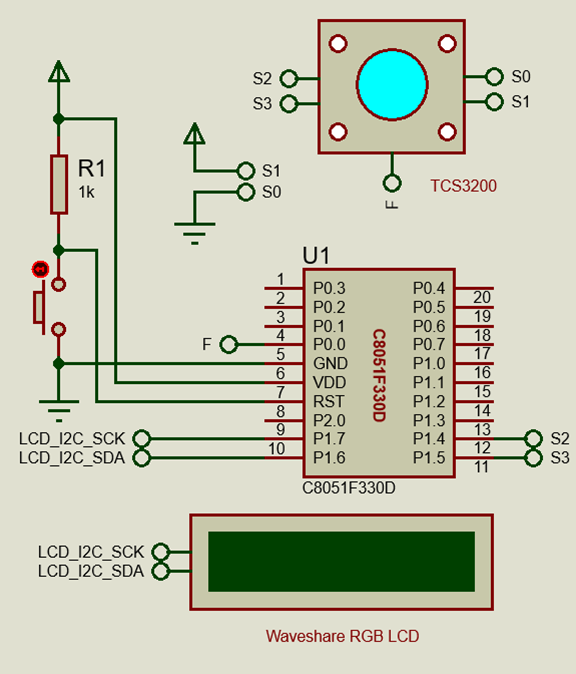
Schematic
Explanation
Some sensors do not communicate using UART, I2C or SPI methods. Such is the case with the TCS3200 colour sensor from TAOS. This sensor is a light-to-frequency output and so we need to convert frequency output to usable data that represents reflected light colour ratios. TCS3200 has four types of photodiode arrays for sensing colours, three of which are sensitive to red, green and blue colours while a single one consists of a clear or no colour filter. Thus, PCA capture is needed to extract colour info.
Since capture mode is time-sensitive, the system clock setting must be known. In this example, the system clock is set to 12.25MHz.
 void Oscillator_Init(void)
 {
     OSCICN = 0x82;
 }
The PCA hardware’s channel 0 is set to capture failing edges with PCA counter overflow and PCA channel 0 (CEX0) interrupts both enabled and a PCA counter time base source of system clock divided by 12 selected.
 void PCA_Init(void)
 {
     PCA0CN = 0x40;
     PCA0MD &= ~0x40;
     PCA0MD = 0x01;
     PCA0CPM0 = 0x11;
 }
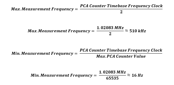
With these settings, the tick resolution of the PCA counter is as follows:
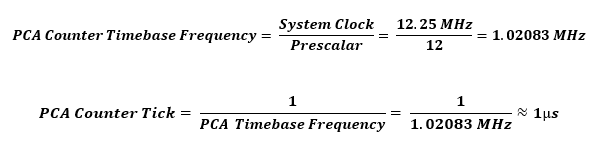
So, in theory, the PCA module can measure the following maximum and minimum frequencies as per Nyquist criterion:
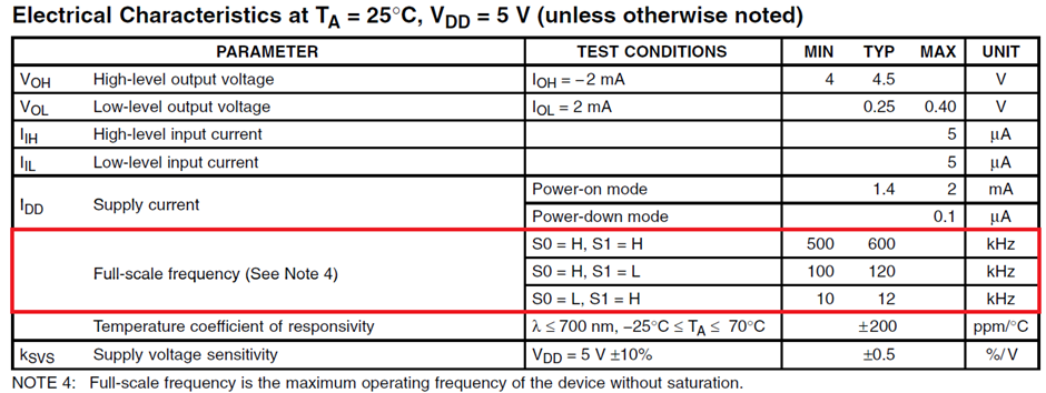
Referring to the electrical characteristics of the sensor as shown below, three ranges of frequency outputs can be obtained from it. The first one would not be suitable as the frequency range exceeds the hardware limit of the PCA module as per the settings discussed. The second and third ones are the preferred ones. I have chosen the last one because this range will not overload the PCA module and the readings would be computed quickly. Note with higher frequency settings, the precision of measurement is largely increased but computation and back-calculation times are increased too.
Now that the theories are established, let us see what happens when falling edges are captured. Whenever a falling edge is detected by the PCA module, the value of the PCA counter is immediately copied to the respective capture-compare register set. Two successive like edges will provide two time captures. The difference between these successive captures results in finding the period. We also need to take into account of any PCA counter overflow that has occurred during these measurements. All these are done inside the PCA interrupt subroutine.
 void PCA0_ISR(void)
 iv IVT_ADDR_EPCA0
 ilevel 0
 ics ICS_AUTO
 {
     if(CF_bit)
     {
         overflow++;
         CF_bit = 0;
     }

     if(CCF0_bit)
     {
         current_capture = get_capture_count();
         count = ((overflow << 16) + (current_capture - past_capture));
         past_capture = current_capture;
         overflow = 0x00000;
         current_capture = 0;
         CCF0_bit = 0;
     }
 }
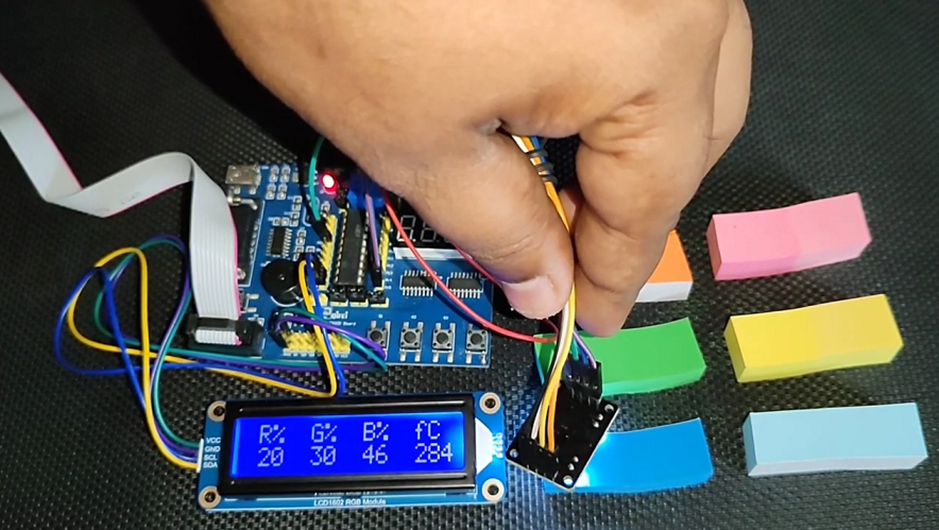
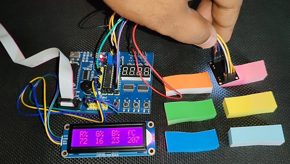
Inside the main loop, the photodiode arrays of the sensor are switched by switching the states of its S2 and S3 inputs. After switching each filter, the respective frequency reading is extracted and stored. The frequency readings are converted to percentages with respect to the clear filter. These percentages represent the amount of colour reflected with respect to the full visible light spectrum. The Waveshare RGB LCD‘s backlight colour tries to mimic the detected colour. This is done by providing RGB data from TCS3200 colour sensor to the PCA9633 IC of the LCD’s RGB backlight driver.
 void main(void)
 {
     unsigned long f = 0;
     unsigned long fr = 0;
     unsigned long fg = 0;
     unsigned long fb = 0;
     unsigned long fc = 0;
     unsigned char mode = 0;

     Init_Device();
     RGB_LCD_init();
     LCD_clear_home();

     LCD_goto(0, 0);
     LCD_putstr(" R%  G%  B%  fC");

     while(1)
     {
         switch(mode)
         {
             case RED_filter:
             {
                 S2 = 0;
                 S3 = 0;
                 break;
             }
             case BLUE_filter:
             {
                 S2 = 0;
                 S3 = 1;
                 break;
             }
             case CLEAR_filter:
             {
                 S2 = 1;
                 S3 = 0;
                 break;
             }
             case GREEN_filter:
             {
                 S2 = 1;
                 S3 = 1;
                 break;
             }
         }
         delay_ms(100);

         f = (1020833 / ((float)count));

         switch(mode)
         {
             case RED_filter:
             {
                 fr = f;
                 break;
             }
             case BLUE_filter:
             {
                 fb = f;
                 break;
             }
             case CLEAR_filter:
             {
                 fc = f;
                 break;
             }
             case GREEN_filter:
             {
                 fg = f;
                 break;
             }
         }

         mode++;

         if(mode > 3)
         {
             fr = (((float)fr / (float)fc) * 100);
             fg = (((float)fg / (float)fc) * 100);
             fb = (((float)fb / (float)fc) * 100);

             print_C(0, 1, fr);
             print_C(4, 1, fg);
             print_C(8, 1, fb);
             print_I(12, 1, fc);

             fr <<= 1;
             fg <<= 1;
             fb <<= 1;
             set_RGB(fr, fg, fb);

             mode = 0;
             delay_ms(400);
         }
     };
 }
Demo
|
|
Thanks for the feedback….