Mastering the SiLabs C8051 Microcontroller
|
|
Analogue Comparator (CP0) – Capacitance Meter
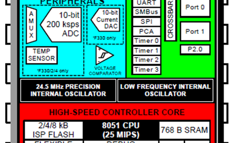
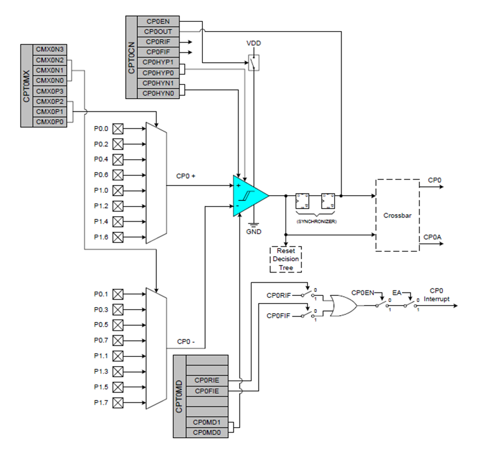
C8051s come with analogue comparator hardware embedded with them. This comparator can be used to measure voltage levels and take decisions based on voltage levels. Analogue comparators can be used as low battery detectors, voltage threshold detectors, oscillators, etc. The block diagram of C8051F330D’s comparator 0 (CP0) is shown below. From the block diagram above, we can see that several inputs can be used. Additionally, there are options for interrupt, hysteresis, synchronizer, output and others.
Code
 #include "LCD_2_Wire.c"
 #include "lcd_print.c"

 #define measure_button     P1_4_bit

 #define sampling_R         10000.0
 #define div_factor         (sampling_R * 0.693147)

 #define us_per_tick        0.9795918
 #define scale_factor       50

 unsigned char ovf = 0;
 unsigned char measurement_done = 0;

 void PCA_Init(void);
 void Timer_Init(void);
 void Comparator_Init(void);
 void Port_IO_Init(void);
 void Oscillator_Init(void);
 void Interrupts_Init(void);
 void Init_Device(void);
 void reset_timer_1(void);
 unsigned int get_timer_1(void);

 void Timer_1_ISR(void)
 iv IVT_ADDR_ET1
 ilevel 0
 ics ICS_AUTO
 {
     ovf++;
     TF1_bit = 0;
 }

 void Analog_Comparator_ISR(void)
 iv IVT_ADDR_ECP0
 ilevel 0
 ics ICS_AUTO
 {
     if(CP0FIF_bit)
     {
         measurement_done = 1;
         TCON = 0x00;
         P0_2_bit = 0;
         CP0FIF_bit = 0;
     }
 }

 void main(void)
 {
     float c = 0.0;
     unsigned long cnt = 0;

     Init_Device();
     LCD_init();
     LCD_clear_home();

     LCD_goto(0, 0);
     LCD_putstr("Capacitance/ F:");

     while(1)
     {
         if((measure_button == 0) && (measurement_done == 0))
         {
             reset_timer_1();
             LCD_goto(0, 1);
             LCD_putstr("Discharging!  ");
             P0MDIN = 0xFE;
             P0MDOUT = 0x06;
             P0_1_bit = 0;
             P0_2_bit = 0;
             delay_ms(4000);
             P0MDIN = 0xFC;
             P0MDOUT = 0x04;
             TCON = 0x40;
             P0_2_bit = 1;
             LCD_goto(0, 1);
             LCD_putstr("Measuring!    ");
             delay_ms(4000);
         }

         if(measurement_done)
         {
            cnt = ovf;
            cnt <<= 16;
            cnt += get_timer_1();
            c = ((cnt * us_per_tick) / div_factor);
            c *= scale_factor;

            LCD_goto(0, 1);
            LCD_putstr("             ");

            if((c > 0.0) && (c < 10000000.0))
            {
                if((c > 0) && (c < 1000))
                {
                    LCD_goto(12, 0);
                    LCD_putstr("n");
                }
                else if((c >= 1000.0) && (c < 10000000.0))
                {
                    c /= 1000.0;
                    LCD_goto(12, 0);
                    LCD_putstr("u");
                }

                print_F(0, 1, c, 1);
            }

            else
            {
                LCD_goto(0, 1);
                LCD_putstr("O.L");
            }

            measurement_done = 0;
         }
     };
 }

 void PCA_Init(void)
 {
     PCA0MD &= ~0x40;
     PCA0MD = 0x00;
 }

 void Timer_Init(void)
 {
     TMOD = 0x10;
 }

 void Comparator_Init(void)
 {
     CPT0CN = 0x8A;
     delay_us(20);
     CPT0CN &= ~0x30;
     CPT0MX = 0x00;
     CPT0MD = 0x11;
 }


 void Port_IO_Init(void)
 {
     // P0.0  -  Skipped,     Open-Drain, Analog
     // P0.1  -  Skipped,     Open-Drain, Analog
     // P0.2  -  Skipped,     Push-Pull,  Digital
     // P0.3  -  Unassigned,  Open-Drain, Digital
     // P0.4  -  Unassigned,  Open-Drain, Digital
     // P0.5  -  Unassigned,  Open-Drain, Digital
     // P0.6  -  Unassigned,  Open-Drain, Digital
     // P0.7  -  Unassigned,  Open-Drain, Digital

     // P1.0  -  Unassigned,  Open-Drain, Digital
     // P1.1  -  Unassigned,  Open-Drain, Digital
     // P1.2  -  Unassigned,  Open-Drain, Digital
     // P1.3  -  Unassigned,  Open-Drain, Digital
     // P1.4  -  Skipped,     Open-Drain, Digital
     // P1.5  -  Unassigned,  Open-Drain, Digital
     // P1.6  -  Skipped,     Push-Pull,  Digital
     // P1.7  -  Skipped,     Push-Pull,  Digital

     P0MDIN = 0xFC;
     P0MDOUT = 0x04;
     P1MDOUT = 0xC0;
     P0SKIP = 0x07;
     P1SKIP = 0xD0;
     XBR1 = 0xC0;
 }

 void Oscillator_Init(void)
 {
     OSCICN = 0x82;
 }

 void Interrupts_Init(void)
 {
     IE = 0x88;
     EIE1 = 0x20;
 }

 void Init_Device(void)
 {
     PCA_Init();
     Comparator_Init();
     Port_IO_Init();
     Oscillator_Init();
     Interrupts_Init();
 }

 void reset_timer_1(void)
 {
     ovf = 0;
     TH1 = 0x00;
     TL1 = 0x00;
 }

 unsigned int get_timer_1(void)
 {
     unsigned int counts = 0;

     counts = TH1;
     counts <<= 8;
     counts |= TL1;

     return counts;
 }
Schematic
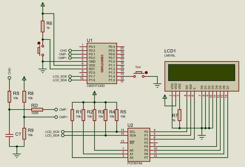
Explanation
In this section, we will see how we can use the internal analogue comparator of a C8051 to measure unknown capacitance values of capacitors. The principle used is based on determining the time it takes to charge an unknown capacitor to a certain voltage level. Thus, two things are needed to be done in the program – firstly, comparing two voltage levels and secondly, timing the time taken for the comparator to change logic state.
The basic circuit looks like the one shown below:
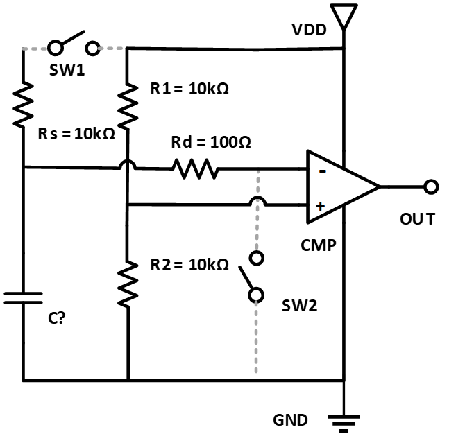
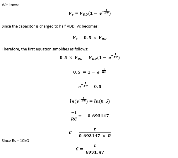
Before trying to measure the unknown capacitor C?, it is discharged through the current-limiting resistor Rd by closing switch SW2. SW2 is not a physical switch. The working of SW2 is done inside the microcontroller. The inverting input pin of the internal analogue comparator is temporarily set as an output and then it is set to logic zero for 4 seconds. The capacitor to be measured starts to discharge. Discharging the capacitor ensures that no residual charge is present in it as such charge will definitely affect reading. After discharging SW2 is opened by declaring it as an input.
After discharging, switch SW1 is closed and an internal timer is started. SW1 is just like SW2 and is not an external pin but rather an I/O pin. The non-inverting pin of the comparator is set to half VDD by the voltage divider formed by resistors R1 and R2. Thus, when SW1 is closed with the unknown capacitor fully discharged, logic high state is observed at the output side of the comparator. The unknown capacitor continues to charge via the sampling resistor Rs. When the voltage of the capacitor exceeds a value more than half VDD, the output state of the comparator is flipped low and SW1 is opened. Thus, a high-low transition is observed. When this transition occurs, the timer is stopped, a comparator interrupt is issued and some calculations are performed to back-calculate the capacitance of the unknown capacitor.
Now let us see the calculations.
P0.0 and P0.1 are set as the open-drain analogue pins since these pins are comparator input pins. P0.2 is the capacitor charging pin or SW1. P1.4 is attached to an onboard push-button that will be used to trigger the measurement process when pressed.
 void Port_IO_Init(void)
 {
     // P0.0  -  Skipped,     Open-Drain, Analog
     // P0.1  -  Skipped,     Open-Drain, Analog
     // P0.2  -  Skipped,     Push-Pull,  Digital
     // P0.3  -  Unassigned,  Open-Drain, Digital
     // P0.4  -  Unassigned,  Open-Drain, Digital
     // P0.5  -  Unassigned,  Open-Drain, Digital
     // P0.6  -  Unassigned,  Open-Drain, Digital
     // P0.7  -  Unassigned,  Open-Drain, Digital

     // P1.0  -  Unassigned,  Open-Drain, Digital
     // P1.1  -  Unassigned,  Open-Drain, Digital
     // P1.2  -  Unassigned,  Open-Drain, Digital
     // P1.3  -  Unassigned,  Open-Drain, Digital
     // P1.4  -  Skipped,     Open-Drain, Digital
     // P1.5  -  Unassigned,  Open-Drain, Digital
     // P1.6  -  Skipped,     Push-Pull,  Digital
     // P1.7  -  Skipped,     Push-Pull,  Digital

     P0MDIN = 0xFC;
     P0MDOUT = 0x04;
     P1MDOUT = 0xC0;
     P0SKIP = 0x07;
     P1SKIP = 0xD0;
     XBR1 = 0xC0;
 }
The comparator is set as follows.
 void Comparator_Init(void)
 {
     CPT0CN = 0x8A;
     delay_us(20);
     CPT0CN &= ~0x30;
     CPT0MX = 0x00;
     CPT0MD = 0x11;
 }
With these settings, the comparator is set with 10mV hysteresis on both inputs, fast response time and falling-edge comparator interrupt.
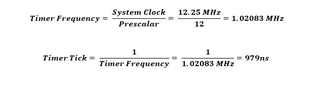
The system clock is set to 12.25MHz using the internal RC oscillator.
 void Oscillator_Init(void)
 {
     OSCICN = 0x82;
 }
The timer used for timing in this example is Timer 1. It is set as a Mode 1 timer with a prescalar of 12 and with overflow interrupt enabled. However, it is not started in the beginning. It will be started during measurement. In this way, one tick of the timer is about 979ns.
 void Timer_Init(void)
 {
     TMOD = 0x10;
 }
The main loop has two parts. The first part is about discharging and charging the unknown capacitor. When the push-button is pressed, the timer is reset and the discharge procedure is started by setting the proper logic states of the pin as mentioned earlier. After completing the discharge procedure, the I/O pins are reconfigured and the timer is started as soon as the charging process is initiated.
 if((measure_button == 0) && (measurement_done == 0))
 {
     reset_timer_1();
     LCD_goto(0, 1);
     LCD_putstr("Discharging!  ");
     P0MDIN = 0xFE;
     P0MDOUT = 0x06;
     P0_1_bit = 0;
     P0_2_bit = 0;
     delay_ms(4000);
     P0MDIN = 0xFC;
     P0MDOUT = 0x04;
     TCON = 0x40;
     P0_2_bit = 1;
     LCD_goto(0, 1);
     LCD_putstr("Measuring!    ");
     delay_ms(4000);
 }
After completing the aforementioned steps, the code waits for the comparator interrupt.
 void Analog_Comparator_ISR(void)
 iv IVT_ADDR_ECP0
 ilevel 0
 ics ICS_AUTO
 {
     if(CP0FIF_bit)
     {
         measurement_done = 1;
         TCON = 0x00;
         P0_2_bit = 0;
         CP0FIF_bit = 0;
     }
 }
When the comparator interrupt is triggered, the timer and the charging process are both stopped.
We have already seen what math is needed to convert timer count to capacitance value and this second part of the main code is all about so.
 if(measurement_done)
 {
     cnt = ovf;
     cnt <<= 16;
     cnt += get_timer_1();
     c = ((cnt * us_per_tick) / div_factor);
     c *= scale_factor;

     LCD_goto(0, 1);
     LCD_putstr("             ");

     if((c > 0.0) && (c < 10000000.0))
     {
          if((c > 0) && (c < 1000))
          {
               LCD_goto(12, 0);
               LCD_putstr("n");
          }

          else if((c >= 1000.0) && (c < 10000000.0))
          {
              c /= 1000.0;
              LCD_goto(12, 0);
              LCD_putstr("u");
          }

          print_F(0, 1, c, 1);
     }

     else
     {
          LCD_goto(0, 1);
          LCD_putstr("O.L");
     }

     measurement_done = 0;
 }
Timer 1 interrupt is used to check if the timer overflowed during measurement. This should only be taken into account when measuring large-value capacitors.
 void Timer_1_ISR(void)
 iv IVT_ADDR_ET1
 ilevel 0
 ics ICS_AUTO
 {
     ovf++;
     TF1_bit = 0;
 }
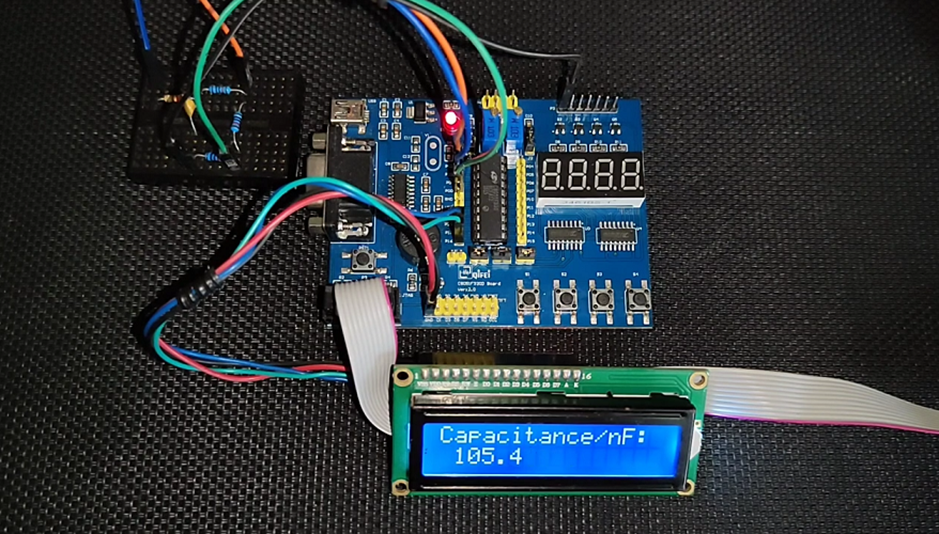
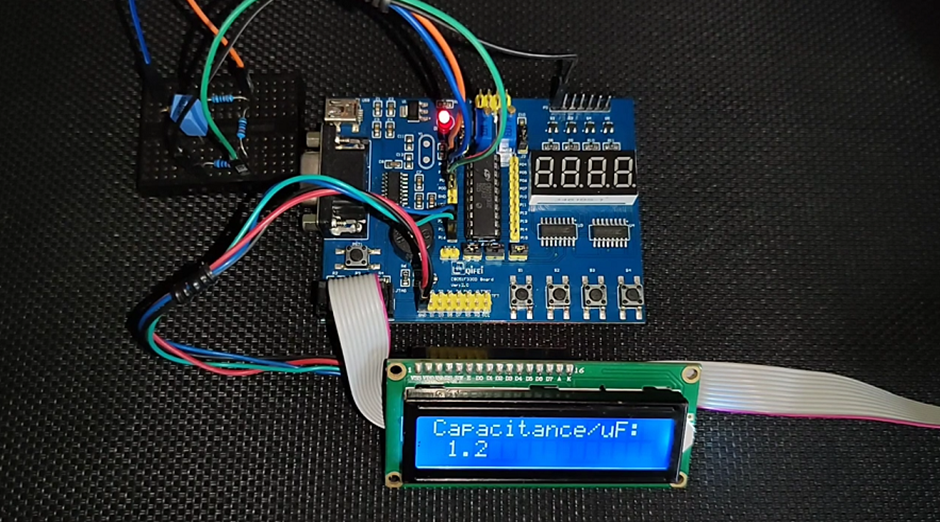
Unlike most other examples covered in this document, an I2C LCD is used to show data. The code for the I2C LCD has been shared and it is the same as the ones I used with my past documents on various platforms.
The overall performance of such a capacitance meter is satisfactory and the results are accurate enough for most cases.
Demo
|
|
Thanks for the feedback….