Mastering the SiLabs C8051 Microcontroller
|
|
External Interrupt (EXTI) – Rotary Encoder
External interrupts (EXTI) are usually not needed unless there are tasks related to GPIO pins that require very high attention. One such task is reading a rotary encoder. Usually, a rotary encoder is not always rotated unless a change is needed. Thus, we can avoid polling its inputs in code and use an external interrupt to monitor for changes.
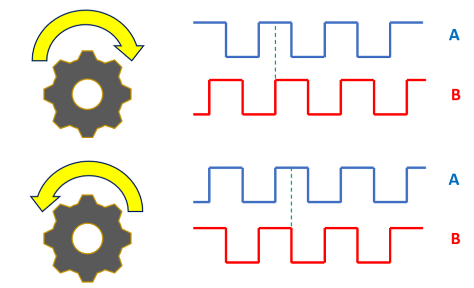
Most rotary encoders have two outputs. They are labelled as A and B or as Data and Clock. A and B have different phase shifts as shown in the diagram above. Let us consider a rotary encode as above. In this situation, we can attach one pin (let’s say A) to an external interrupt of a C8051 and poll the other pin (let’s say B) inside the interrupt for its previous and present state. In this way, we can determine if the rotary encoder is rotating in a clockwise or anticlockwise direction.
Code
 #define LED_DOUT           P1_6_bit
 #define LED_CLK            P1_5_bit
 #define LED_LATCH          P1_7_bit

 #define ROT_ENC_DATA       P0_0_bit
 #define ROT_ENC_CLK        P0_1_bit
 #define ROT_ENC_SW         P0_2_bit

 unsigned char i = 0;
 unsigned char val = 0;
 unsigned char past_clock_state = 0;
 unsigned char present_clock_state = 0;
 unsigned char data_state = 0;
 signed int value = 0;
 unsigned int step_size = 1;

 const unsigned char code segment_code[12] =
 {
   0xC0, // 0
   0xF9, // 1
   0xA4, // 2
   0xB0, // 3
   0x99, // 4
   0x92, // 5
   0x82, // 6
   0xF8, // 7
   0x80, // 8
   0x90, // 9
   0x7F, // .
   0xBF  // -
 };

 const unsigned char code display_pos[4] =
 {
   0xF7, //1st Display
   0xFB, //2nd Display
   0xFD, //3rd Display
   0xFE  //4th Display
 };

 void PCA_Init(void);
 void Timer_Init(void);
 void Port_IO_Init(void);
 void Oscillator_Init(void);
 void Interrupts_Init(void);
 void Init_Device(void);
 void write_74HC595(unsigned char send_data);
 void segment_write(unsigned char disp, unsigned char pos);

 void EXTI_0_ISR(void)
 iv IVT_ADDR_EX0
 ilevel 0
 ics ICS_AUTO
 {
     present_clock_state = ROT_ENC_CLK;
     data_state = ROT_ENC_DATA;

     if(present_clock_state != past_clock_state)
     {
         if(data_state != present_clock_state)
         {
             value -= step_size;
         }
         else
         {
             value += step_size;
         }

         past_clock_state = present_clock_state;
     }

     if(value > 9999)
     {
         value = 0;
     }

     if(value < 0)
     {
         value = 9999;
     }
 }

 void Timer_3_ISR(void)
 iv IVT_ADDR_ET3
 ilevel 1
 ics ICS_AUTO
 {
     switch(i)
     {
         case 0:
         {
             val = (value / 1000);
             break;
         }
         case 1:
         {
             val = ((value % 1000) / 100);
             break;
         }
         case 2:
         {
             val = ((value % 100) / 10);
             break;
         }
         case 3:
         {
             val = (value % 10);
             break;
         }
     }

     segment_write(val, i);

     i++;

     if(i > 3)
     {
        i = 0;
     }

     TMR3CN &= 0x7F;
 }


 void main(void)
 {
     Init_Device();

     while(1)
     {
         if(ROT_ENC_SW == 0)
         {
             delay_ms(60);
             while(ROT_ENC_SW == 0);
             step_size *= 10;

             if(step_size > 1000)
             {
                 step_size = 1;
             }
         }
     };
 }

 void PCA_Init(void)
 {
     PCA0MD &= ~0x40;
     PCA0MD = 0x00;
 }

 void Timer_Init(void)
 {
     TCON = 0x01;
     TMR3CN = 0x04;
     TMR3RLL = 0x02;
     TMR3RLH = 0xFC;
 }

 void Port_IO_Init(void)
 {
     // P0.0  -  Skipped,     Open-Drain, Digital
     // P0.1  -  Skipped,     Open-Drain, Digital
     // P0.2  -  Skipped,     Open-Drain, Digital
     // P0.3  -  Unassigned,  Open-Drain, Digital
     // P0.4  -  Unassigned,  Open-Drain, Digital
     // P0.5  -  Unassigned,  Open-Drain, Digital
     // P0.6  -  Unassigned,  Open-Drain, Digital
     // P0.7  -  Unassigned,  Open-Drain, Digital

     // P1.0  -  Unassigned,  Open-Drain, Digital
     // P1.1  -  Unassigned,  Open-Drain, Digital
     // P1.2  -  Unassigned,  Open-Drain, Digital
     // P1.3  -  Unassigned,  Open-Drain, Digital
     // P1.4  -  Unassigned,  Open-Drain, Digital
     // P1.5  -  Skipped,     Push-Pull,  Digital
     // P1.6  -  Skipped,     Push-Pull,  Digital
     // P1.7  -  Skipped,     Push-Pull,  Digital

     P1MDOUT = 0xE0;
     P0SKIP = 0x07;
     P1SKIP = 0xE0;
     XBR1 = 0x40;
 }

 void Oscillator_Init(void)
 {
     OSCICN = 0x82;
 }

 void Interrupts_Init(void)
 {
     IE = 0x81;
     IP = 0x01;
     EIE1 = 0x80;
 }
 void Init_Device(void)
 {
     PCA_Init();
     Timer_Init();
     Port_IO_Init();
     Oscillator_Init();
     Interrupts_Init();
 }

 void write_74HC595(unsigned char send_data)
 {
     signed char clks = 8;

     while(clks > 0)
     {
         if((send_data & 0x80) == 0x00)
         {
           LED_DOUT = 0;
         }
         else
         {
           LED_DOUT = 1;
         }

         LED_CLK = 0;
         send_data <<= 1;
         clks--;
         LED_CLK = 1;
     }
 }

 void segment_write(unsigned char disp, unsigned char pos)
 {
     write_74HC595(segment_code[disp]);
     write_74HC595(display_pos[pos]);
     LED_LATCH = 0;
     LED_LATCH = 1;
 }
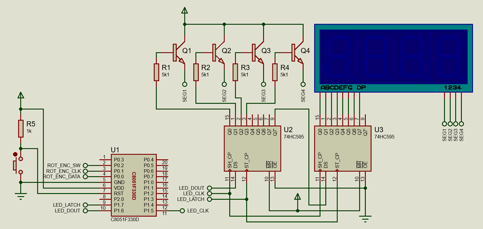
Schematic
Explanation
Unlike most other examples, this example is not clock dependent. All we need are an external interrupt and a couple of GPIO pins as inputs.
 #define ROT_ENC_DATA       P0_0_bit
 #define ROT_ENC_CLK        P0_1_bit
 #define ROT_ENC_SW         P0_2_bit
Now let’s see the theory. Suppose the clock pin is attached to the interrupt pin.
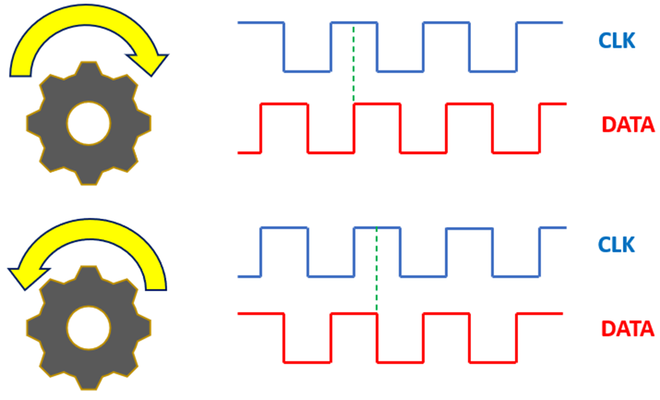
As soon as an interrupt is triggered, both the data and the clock pins are polled. If there is a change in the logic state of the clock input then the state of the data pin is compared against the current state of the clock pin. This comparison tells us the direction of the rotary encoder. Based on direction a variable named value is either increment or decremented.
 void EXTI_0_ISR(void)
 iv IVT_ADDR_EX0
 ilevel 0
 ics ICS_AUTO
 {
     present_clock_state = ROT_ENC_CLK;
     data_state = ROT_ENC_DATA;

     if(present_clock_state != past_clock_state)
     {
         if(data_state != present_clock_state)
         {
             value -= step_size;
         }
         else
         {
             value += step_size;
         }
         past_clock_state = present_clock_state;
     }
     if(value > 9999)
     {
         value = 0;
     }
     if(value < 0)
     {
         value = 9999;
     }
 }
The step size of the change is determined in the main.
 if(ROT_ENC_SW == 0)
 {
     delay_ms(60);
     while(ROT_ENC_SW == 0);
     step_size *= 10;

     if(step_size > 1000)
     {
          step_size = 1;
     }
 }
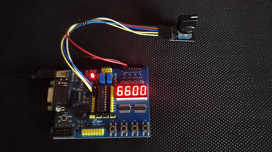
Demo
|
|
Thanks for the feedback….